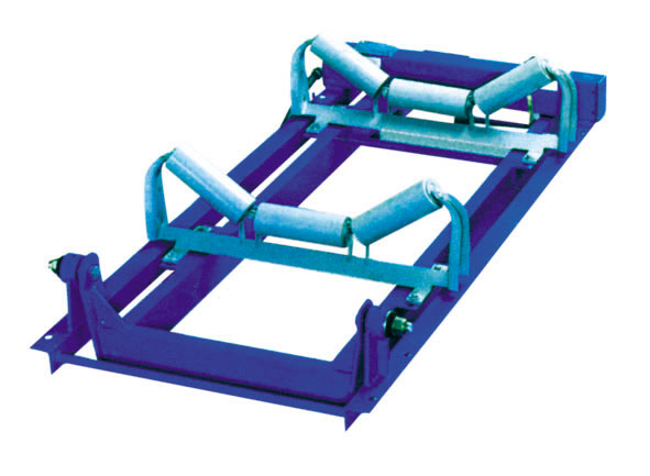
The weighing frame part
Electronic belt scale zero, abnormal flow should first check the scale frame part whether there is a problem. The main problems of the scale are as follows:
1. The lever is stuck
2. Belt running off track
3. The return trip belt touches the weight sensor boom
Scale frame part should often be inspected, problems can be found intuitively, but also easy to solve.
Weight signal fault and troubleshooting
The weighing sensor is the core part of the electronic belt scale. Once damaged, it cannot be repaired and can only be replaced. The phenomenon is that the meter displays abnormal flow, which needs to be checked:
1. The driving voltage of the weighing sensor is 10VDC
2. The signal voltage should be close to the original recorded zero output voltage when no load is on
3. The measured signal voltage OAP type should not exceed 30mVDC at full load
4, shut off the power supply, weighing signal from the instrument, measured with a multimeter incentives between two line should be about 380 Ω, signals between two lines should be around 350 Ω.
5. Check whether the connection between the cable, instrument and sensor is firm, short circuit or broken. For the cable because the cable is not long enough, but several cables connected to the signal line should be more attention. Cable cable several core connector staggered as far as possible. The joints shall be soldered and insulated.
Speed signal fault and troubleshooting
Phenomenon: after the conveyor starts, the flow rate is "0", and the increased material flow rate is "0".
The material on the belt is basically uniform, and the meter shows a wide range of flow changes.
The main technical data of the velocity sensor are as follows:
Resistance: around 130 Ω
Output voltage: between 4 and 30V VAC, the faster the speed, the higher the voltage
Maintenance: open the belt after measuring the motherboard voltage terminal 9, 10 and original records, as well as whether or not, if no voltage, stopped a belt, shut off the power supply, remove the line 9, 10, with three table was used to measure the resistance shall be the 130 Ω, such as the resistance value is wrong, possible sensor or bad cable turn around or break off, speed measuring sensor junction box cover to live apart, check whether the connection is secure, measuring the resistance, if still wrong sensor output line may break or damage of sensors.
If the resistance value of the sensor meets the requirements, that is, there is no voltage output. Check whether the connection between the sensor and the speed measuring drum is reliable. If the drum turns, the speed measuring sensor also turns, the connection is reliable. Remove the cover, then remove the speed sensor, with a multimeter to measure resistance, such as resistance meets the requirements, use hand screw shaft speed sensor, make its rotation, the output voltage should be around 10 vac, fast speed, high output voltage, the speed sensor is good, to recover the sensor installed, output wire and cable connected and the check meter terminal 9, 10 and instrument shell or other wire touching one another, checked all the information, the fault is ruled out, after startup display instrument with flow.
Under the condition of the instrument all work (check), the flow of the instrument shows changed (basic material constant, check the instrument zero time and zero sometimes long, sometimes zero time is short, this kind of phenomenon, is the speed sensor shaft connection of fastening bolt on the axle housing and loose, turn don't turn, when a sensor that is lost, causing unstable flow. Tighten the fastening screw. The pressure between the measuring drum and the belt and the wrap Angle are not enough, can also cause loss of rotation.

Instrument fault and troubleshooting
1. No display
Phenomenon: no display screen.
Check the power outlet for electricity.
Check whether the three power cords on the terminals are properly connected (L1, L2, CON3).
Check that the flat cable from the main board to the display is connected properly.
Check whether the fuse of the power outlet (with a spare) and the main board are fused.
Check whether the CPU power supply on the main board is normal.
Use three meters to measure whether L1 and L2 have 220VAC voltage.
Switching power supply may sometimes produce a fault, if the voltage is not normal or not, the fault may be switching power supply.
2. freezes
Phenomenon: the key does not work and the flow does not change.
Reasons: one is the external interference caused by the crash, the other is the instrument itself fault.
First, make visual inspection: check whether all the wiring on the terminal of the main engine board is reliable or not
Check the integrity of each plug-in IC
Check the mainboard voltage is normal
Interference crash, fault easy to eliminate, cold start to the instrument, the fault can be eliminated
The instrument itself fault crash, is generally caused by a chip damage, if the chip can not be removed, it should be repaired by professional personnel.
3. Display confusion
(1) external interference
(2) the internal connection line is not reliable
(3) power failure is not maintained
Handling: handling of external interference: the 220VAC power supply shall be well grounded, and the voltage between the power line "0" and the ground shall be close to zero VAC with three meters, otherwise it shall be ungrounded or ungrounded.
The power supply of the instrument should be separated from other electrical equipment (such as high-power motor, electric bell, hand drill) which is easy to produce electric spark. The electric bell and hand drill should not be used near the instrument, especially the welding machine should not be used. If it must be used, the power of the instrument can be turned off first, and then the instrument can be restored after work.

 TEL:133-0520-1772


